Guide to Hydrant Flow Testing
Learn how to conduct a fire hydrant flow test safely and accurately

This guide is designed to be a primer on how to conduct a fire hydrant flow test. The following information has been sourced from the National Fire Protection Association's (NFPA) 291 guide "Recommended Practice for Water Flow Testing and Marking of Hydrants."
You can view the NFPA guide here.
Before continuing, be sure to stay informed with similar content by signing up for notifications.
The purpose of flow tests
Flow tests are conducted for many reasons. WSRB uses flow tests to determine the amount of available water in a water system at 20 psi residual pressure. The amount of available water is then compared to the water required to suppress fires in selected buildings during our protection class rating of a community.
The basic premise behind the tests is to “discharge water at a measured rate of flow from the system at a given location and observe the corresponding pressure drop in the mains.”
Each flow test collects information on three different forms of pressure:
- Static pressure – water main pressure under normal, non-flowing conditions
- Residual pressure – water main pressure when water is flowing
- Pitot pressure – the flow pressure at the outlet(s) of the flowing fire hydrant(s)
Additionally, flow tests allow communities to accurately color-code their fire hydrants, providing firefighters with the water-flow capabilities of each individual fire hydrant. Here is a list of what each fire hydrant color represents:
- Red indicates a water-flow capacity of less than 500 gpm
- Orange indicates a water-flow capacity of 500 to 999 gpm
- Green indicates a water-flow capacity of 1,000 to 1,499 gpm
- Blue indicates a water-flow capacity of 1,500 or greater gpm
Learn more about fire hydrant colors in our blog on the subject.

Conducting a flow test
Hydrant flow testing should only be conducted by properly trained personnel in conjunction with water department personnel.
For a detailed step-by-step guide to conducting a hydrant flow test, reference the current edition of NFPA 291, available here.
Be prepared to record the following information during the test:
- Date of hydrant flow test
- Location of hydrants being tested (street address and/or cross streets)
- Time of day testing was performed
- Static reading at the static/residual hydrant (pressure in the system with no flow)
- Residual reading at the static/residual hydrant (pressure in the system during flow)
- Flow reading at the flow hydrant(s), using a pitot gauge
- Hydrant outlet size and type (determining the coefficient of discharge)
NFPA recommends you have at least the following pieces of equipment to properly conduct a flow test:
- 200 psi pressure gauge with 1 psi graduations
- Several pitot tubes with gauges
- Hydrant wrenches
- Hydrant cap, 2½ inch, tapped with a T connection for the 200 psi gauge and a cock at the end for relieving air pressure
Step One
Select a grouping of hydrants that are within the same vicinity. Depending on the size of the overall water system, 2 or more hydrants should be selected for the test. When selecting hydrants, make sure to inspect each for obvious damage and/or defects – do not use damaged or defective hydrants and immediately report them for repair.
Step Two
Consider potential damage to surroundings and potential flooding problems that could occur. Make sure nearby drains are uncovered and ensure discharged water has a safe place to go.
Step Three
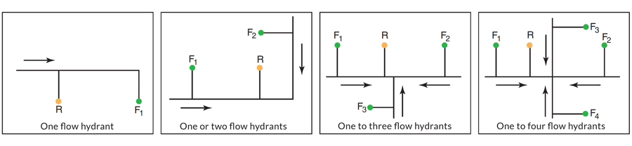
Select one of the chosen fire hydrants to be designated as the static/residual hydrant – this will be where both the normal static pressure will be observed with the other hydrants in the group closed and the residual pressure will be observed with the other hydrants in the group flowing. Record the location of all the hydrants to be used in the test. According to the NFPA, this hydrant should be “chosen so it will be located between the hydrant(s) to be flowed and the large mains that constitute the immediate sources of water supply in the area.” Here is a visual representation of various test layouts (R represents the residual hydrant and F represents the hydrant(s) to be flowed):
Step Four
Remove the 2½ inch cap on the static/residual hydrant and attach the hydrant cap with 200 psi gauge and air relief valve open to the outlet. Open the hydrant valve slowly and completely until water flows out of the air relief valve then shut the valve. Allow a few minutes for the pressure reading on the gauge to stabilize. The stabilized reading on the gauge represents the static pressure. Record this pressure reading.
Step Five
Remove the cap(s) on the flow hydrant(s) of the hydrant ports to be flowed. Pitot pressure readings for each port flowed will need to be measured and recorded. There are several ways to attain a pitot pressure from a flowing hydrant.
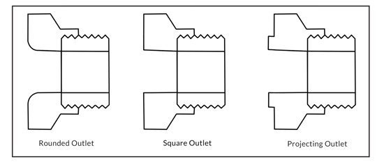
If you are using a hand-held pitot gauge, check to see if the opening on each port is rounded, square, or projecting. This will help to determine the correct coefficient of discharge to use.
If you are using stream straighter, flow diverters, diffusers or other flow test equipment attach this equipment to the hydrant port(s) to be flowed ensuring the water is discharged to a safe place.
Open the hydrants to be flowed and allow the hydrants to flow for a sufficient amount of time in order to clear all debris from the stream(s).
Step Six
Use a pitot gauge to simultaneously measure the velocity pressure of each stream flowing out of the flow hydrant(s). If you are using a hand-held pitot gauge, measure the pressure with the gauge in the center of the flow stream at a distance of ½ the outlet diameter from the port or stream straighter opening. Flow test equipment with a built-in pitot gauge can make this step easier.
At the same time, take a second pressure reading at the static/residual hydrant. This reading on the gauge represents the residual pressure.
Step Seven
After recording all the pressures from the residual and flow hydrants, slowly close the flow hydrant(s).
Step Eight
Take another static pressure reading at the static/residual hydrant. This reading should be remarkably close to your initial static pressure reading at the beginning of the flow test. If this second reading is significantly higher or lower than your first, consult with the water department to determine why. If this second reading is the same or close to the same as your first reading, you can slowly close the hydrant.
A few things to note while conducting a flow test:
- When the tests are complete, the records should be filed for future reference by interested parties.
- Tests should be made during a period of ordinary demand. Increased flow demand on the water system could set off alarms at both the water plant and connected fire protection systems in nearby buildings.
- Water customers may experience temporary “dirty water” – that is water that has been tainted by sediment or rust stirred up by the increased flow during the test. Ensure the water expelled during the test does not cause damage to property or impede pedestrian or vehicle traffic.
- All pressure gauges should be calibrated regularly, at least once every year.

Calculate flow test results
At each hydrant outlet flowed during the test, the discharge (Q) in gallons per minute (gpm) is determined from the measurements of the diameter of the outlets flowed (d), the pitot pressure (p) of the water streams as indicated by the pitot gauge readings, and the coefficient (c) of the outlet being flowed using the following formula:
Q = 29.84cd2√p
Q = flow (gallons per minute)
c = coefficient of discharge, which represents friction loss
d = diameter of the outlet (inches)
p = pitot pressure (psi)
To make calculating the hydrant discharge rate easier, attached to this article is a form you can use to easily determine the results of your flow testing.

Using the correct coefficient of discharge is critical for accurate results. If the pitot pressure was measured off the bare hydrant port, use one of the following coefficients based on the port shape discussed previously. 0.90 for rounded outlets, 0.80 for square outlets, and 0.70 for projecting outlets.
If during the test you used a stream straightener on the flowing hydrant port(s) use .95 for the coefficient unless another coefficient is known for the device.
Discharge coefficients may change if you are using different equipment - follow manufacturers' specifications to get accurate results.
When using diffusers to measure the pitot pressure during a flow test the discharge (Q) in gallons per minute (gpm) can be calculated using the same formula as above and adjusting coefficient of discharge (c) and the diameter of the outlet (d) for the diffuser used.
For more information on accurately calculating flows using diffusers please reference this paper.
If more than one outlet is used, the discharges from all outlets are added to obtain the total gallons per minute flowed.
If it is necessary to use the pumper outlet (defined as 4-inches or larger) for the hydrant flow test, an additional factor must be applied to the calculated result to obtain an accurate reading. In these cases, the Q result must be multiplied by a specific factor corresponding to the psi reading. Here is a table that shows the factor to use based on the psi:

Now that the flow gpm for the test hydrant(s) is known, the gpm available at 20 psi can be calculated using the following formula:
Q R = Q F x ( h r / h f ) 0.54
Q R = flow predicted at desired residual pressure (gpm)
Q F = total flow measured during test (gpm)
h r = pressure drop to desired residual pressure (psi)
h f = pressure drop measured during test (psi)
This calculation is also included in the flow test calculation form.
How often do tests need to occur?
The NFPA states that “public fire hydrants should be flow tested every five years to verify capacity and marking of the hydrant.” Additionally, fire hydrants should be inspected at least annually to verify operation, address repairs, and verify reliability.
Common mistakes
Using a single hydrant in the test instead of multiple hydrants
At a minimum, flow testing requires at least two hydrants to collect accurate results and determine the available water supply in a water main. According to the NFPA, “the number of hydrants to be used in any test depends upon the strength of the distribution system in the vicinity of the test location”
If the mains are small and the overall system is weak, only 1-2 hydrants need to be flowed. However, if the mains are large and the overall system is strong, as many as 7-8 hydrants need to be flowed. Several hydrants flowing may be needed to achieve the 10% pressure drop between static and residual pressures.
Improper test layout for hydrants
The static/residual hydrant should be between the flow hydrant(s) and the water supply. Reference the diagram under Step Three of the flow test process to get a better understanding of the best location for the static/residual hydrant.
Inadequate pressure drop between static and residual pressures
To obtain satisfactory results, there needs to be a drop in pressure of at least 10% between the static and residual pressures. If the pressure drop is less than 10%, the flow test should be conducted again with additional ports or hydrants flowing.
Incorrect coefficient of discharge used in flow calculations
The coefficient is dependent on the port flown and equipment used. Be sure to use the correct coefficient to obtain accurate flow test data. If you use equipment not specified in this guide, follow manufacturers' specifications to attain accurate results.
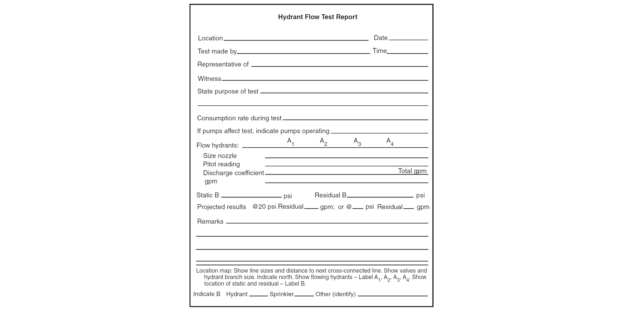
Poor record-keeping of flow tests
This is a matter of keeping test results in a standardized and safe place. Ensure that all hydrant flow tests are recorded and filed for future reference. The NFPA has a hydrant flow test document (example below) which you can fill out while conducting each test, making it easier to standardize and organize your results.
Any questions?
We hope this guide has provided you with a straightforward understanding of how to conduct a fire hydrant flow test. If you need further instruction, please reference the NFPA guide for flow testing or contact our Customer Service team at 206-217-0101, Monday through Friday between 7:30 a.m. and 4 p.m.

